STG35 Welder
Benefits of STG35 Welder
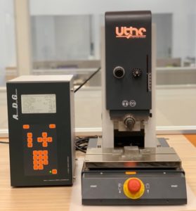
Operating Frequency: 35kHz
Switches: Two-hand start with EMERGENCY STOP at the front
Drive type: Pneumatic double acting cylinder 40mm diameter
Maxiumum Force: 745N at 6 bars compressed air
Maximum Stroke: 50mm
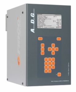
Compatible Generator: ADG35-900 (35kHz, 900 watts)
Precision, Micrometer Style Mechanical Stop Adjustment
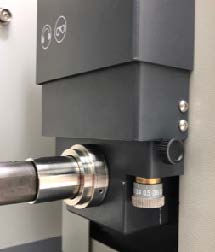
1. Allows for easy and precise setting of the maximum travel of the weld head, protecting the tooling from unnecessary contact.
2. 01.mm increments.
3. Lockable.
Heavy Steel leveling Base Plate with T-slot and mounting holes
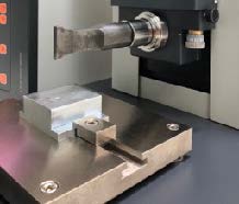
1. Solid base with substantial mass for improved acoustical properties, providing a very repeatable welding process.
2. Built-in leveling capability make setup easy. This also means that nests do not require their own means of leveling, keeping fixturing costs to a minimum.
3. T-slotted base provides the simplest mounting method available while offering extreme flexibility in alignment.
Pressure Regulator DR
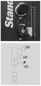
The pressure regulator holds the air pressure on the top side of the piston constant and is set to a height which depends on the size of the piece and the length of the weld joint as well as on the material to be welded.
As a point of reference, a regulated pressure of approx. 3 [bar] can be set for a circular piece of 50 mm in diameter which is welded around the edges.
Throttle VD
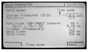
The regulator pressure or system pressure is automatically shown to the ADG display (1). The throttle setting is a function which must be input separately (menu information).
The throttle has two functions :
• It reduces the speed on the last 30 mm of the machine stroke.
• It reduces the time power development when the horn sets up on the plastic piece.
Benefits of ADG Generator
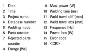
Data string
• For aspects of quality control and retrace ability of weld parts, programs are often used which can accept the necessary data via an interface.
• With ADG it is possible to output a data string at the end of the welding cycle via the serial interface (RS232).
• The output can be switched off or on. Equally, the interval of the output can be determined.
Structure of the data string
The following parameters are displayed in the order listed, separated by a semicolon (;). At the end of the data string a <CR> is sent.